Beginner Robotics Kit - 3. Electronic Assembly

The heart of the robot is the Julieta board. It makes the electric current flow from the batteries to the motors, based on the programming that we are going to develop. It receives information from the sensors, has buttons and is extremely versatile for robotic projects, not only for mobile robots like robotic arms, hexapods, etc. Let's get to know this excellent platform a little better.
The Julieta board was developed to be the most versatile option possible for robotics applications. It has a 3-pin standard input/output bus so you can easily connect sensors, modules, servo motors, etc. In addition, an integrated H-Bridge chip allows you to control motors independently by sending up to 2A of current to each one.
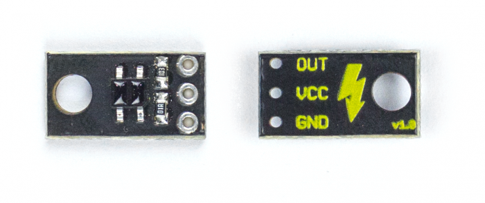
The QRE reflectance sensor is the sensor that gives your robot the ability to detect lines. The sensor works by detecting the reflected light that comes out of its own infrared LED. By measuring the amount of reflected infrared light, it can detect transitions between a dark line and a light surface. The sensor has 3 pins that must be connected to the Julieta board through the female-female jumper cables. The sensor output signal is of the analog type, so it must be connected to an analog pin. The FalconRobot library will make using this sensor simple and practical.
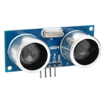
The ultrasonic distance sensor allows your robot to not only detect an object positioned in front of the robot, but also tells the exact distance of that object. With similar operation to sonar, the sensor emits an not audible sound and waits for the signal to return to its receiver. By calculating the time it takes for the sound to return, you can find out the exact distance the object is.
Unlike the line sensor, this sensor has a digital signal, so it must be connected to Julieta's digital pins. It has 4 pins that must be connected to the board via female-female jumper cables.
The time has come to connect the sensors and motors to the Julieta board so that it is possible to move the robot and identify lines and objects! The table below shows where each pin should be connected:
Julieta
The Julieta board was developed to be the most versatile option possible for robotics applications. It has a 3-pin standard input/output bus so you can easily connect sensors, modules, servo motors, etc. In addition, an integrated H-Bridge chip allows you to control motors independently by sending up to 2A of current to each one.
A brief tour of the board
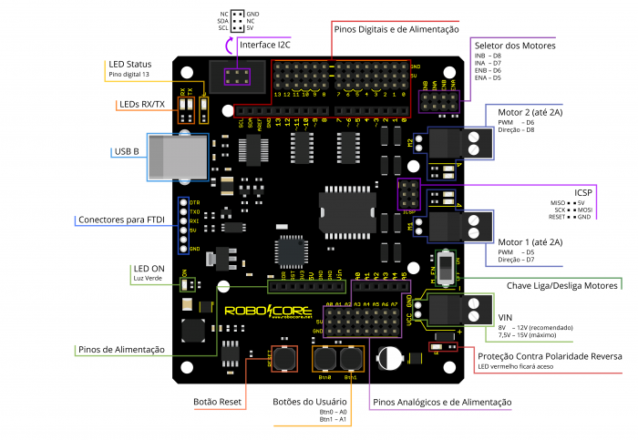
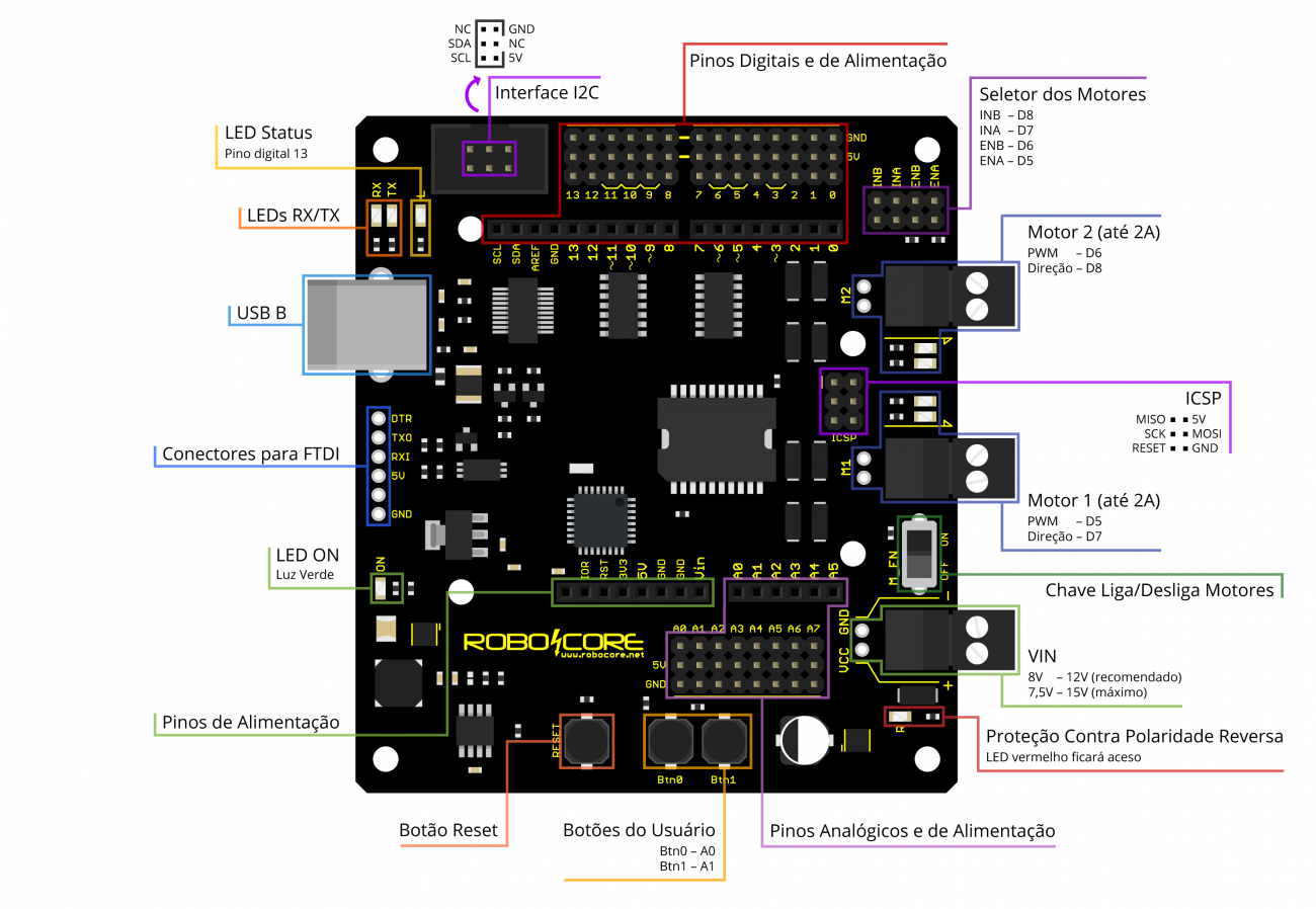
Below we present some characteristics of Julieta. If you do not understand any information, do not worry, what we will use in the experiments of this tutorial will be explained further below. If you have any questions about Julieta, always count on RoboCore's specialized technical support.- USB B: USB connector through which the board is programmed and communicates with the computer.
- RX/TX LEDs: indicate communication on the USB port. They usually flash quickly when the card is reprogrammed or when there is communication between the card and a computer.
- Status LED: connected to pin 13 of the board, this LED can indicate whether the code has been loaded and whether it is running. It is also widely used for general purposes.
- I2C interface: connector in IDC format, provides pins A4 (SDA) and A5 (SCL) allowing easy connections to I2C devices.
- Digital Pins: bus that contains the digital pins of the board. Each pin is provided in a 3-pin connector that also contains a GND and 5V pin.
- Motor Selector: jumpers responsible for connecting the Julieta microcontroller pins to the integrated H-Bridge chip pins (ENA - D5, ENB - D6, INA - D7 and INB - D8) .
- Motor 2: output for motor 2. It can drive a total load of up to 2A. Controlled by pins D6 and D8 (PWM and Direction, respectively).
- ICSP: connector for recording using external programmer. It also provides pins for the SPI bus on the board.
- Motor 1: output for motor 1. It can drive a total load of up to 2A. Controlled by pins D5 and D7 (PWM and Direction, respectively).
- Motor On / Off Switch: motor enable and disable switch. Note: this switch does not turn off the logic part of the board, it just prevents the electric current from going to the motors.
- VIN: voltage input from the battery or motor power supply.
- Reverse Polarity Protection: a red LED is lit when the power supply is connected with the polarity reversed.
- Analog Pins: bus that contains the board's analog input pins. Each pin is provided in a 3-pin connector that also contains a GND and 5V pin.
- User buttons: two buttons for general use on pins A0 and A1. The board's internal pull-up resistors must be enabled for use.
- Reset button: returns the code flow on the board to the beginning when pressed. This button does not delete the card code.
- Power Pins: provide pins with GND, 3.3V, 5V and VIN for general use.
- LED ON: indicates that the board is powered. When lit, it indicates that the battery/power source or the USB cable is connected.
- Connector for FTDI: allows the use of an external USB-Serial converter in case the FTDI of the board is damaged.
Line Sensor
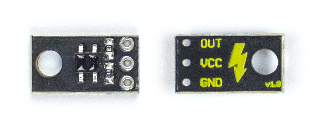
The QRE reflectance sensor is the sensor that gives your robot the ability to detect lines. The sensor works by detecting the reflected light that comes out of its own infrared LED. By measuring the amount of reflected infrared light, it can detect transitions between a dark line and a light surface. The sensor has 3 pins that must be connected to the Julieta board through the female-female jumper cables. The sensor output signal is of the analog type, so it must be connected to an analog pin. The FalconRobot library will make using this sensor simple and practical.
Distance Sensor

The ultrasonic distance sensor allows your robot to not only detect an object positioned in front of the robot, but also tells the exact distance of that object. With similar operation to sonar, the sensor emits an not audible sound and waits for the signal to return to its receiver. By calculating the time it takes for the sound to return, you can find out the exact distance the object is.
Unlike the line sensor, this sensor has a digital signal, so it must be connected to Julieta's digital pins. It has 4 pins that must be connected to the board via female-female jumper cables.
Making connections
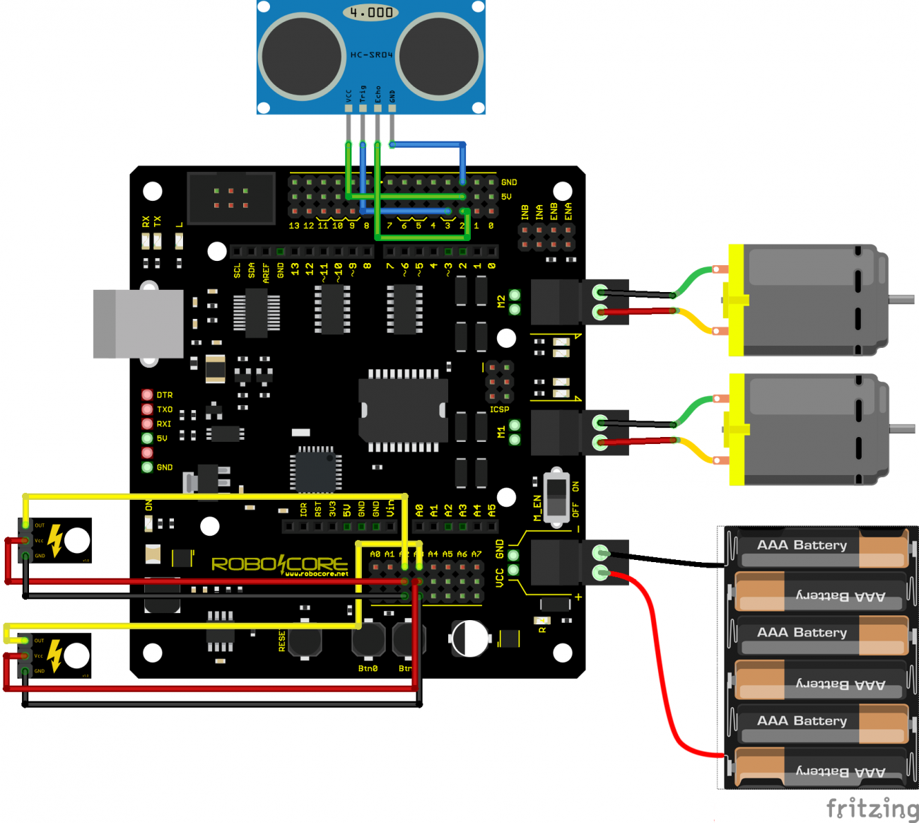
The time has come to connect the sensors and motors to the Julieta board so that it is possible to move the robot and identify lines and objects! The table below shows where each pin should be connected:
| Pin | Julieta | |
|---|---|---|
Distance Sensor |
GND | GND |
| VCC | 5V | |
| ECHO | D2 | |
| TRIG | D3 | |
Line Sensors |
GND | GND |
| VCC | 5V | |
| OUT Left | A2 | |
| OUT Right | A3 | |
Motors |
Left | M1 |
| Right | M2 |
Warning: Leave it to connect the battery wires last, only when you are sure that everything else is connected correctly. Remember to insert the batteries in the battery holder correctly.
See in the diagram below how you should connect the sensors and motors to your Juliet board. Warning: remove the battery, USB cable or any other power source from your board before making any changes to the connections. Making or modifying the connections with the energized board can cause permanent damage to the components.