Motors Control with the Vespa

Introduction
Got your Vespa and want to know how to use it? Don't worry, we're here to help you with these first steps and to show you how to use the basic functions of the library developed for it.
In this tutorial you will see how to drive DC motors using the Vespa, the behavior of each motor control function in the Vespa library and how it can be applied in practice.
List of Materials

Lista completa de produtos
comprar
Vespa


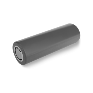
Suporte para 2 Baterias Li-Ion 18650
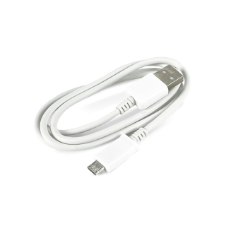
Cabo USB Micro B 80cm
Attention: the 3-6V DC motors with Gear Reduction and Dual Shaft, when purchased separately as in the list above, are not shipped with soldered wires, therefore it will be necessary to solder the motor terminals using cables electrical, such as this (regardless of color).
Note: The recommended 18650 batteries listed above are rechargeable, and they must be charged using a suitable charger (such as this one, for example).
Circuit
To control DC motors with the Vespa, just connect the wires soldered on the motors terminals to the removable terminal blocks on the Vespa, as shown in the electrical diagram below. The wires from the 18650 battery holder must also be connected to the terminal block on the board, closest to the micro USB connector. However, in this case, pay attention to the polarity.

To connect the wires to the Vespa terminals, it is necessary to unscrew the contacts and then "press" the exposed part of the wires, screwing the contact back in, as shown in the video below.
First Control
In this first project, we'll just show how to drive the motors forward and backward.
Code
To control the DC motors, we will use the Vespa library, so to install it, follow the steps in the tutorial First Steps with the Vespa.
As mentioned before, in this first contact we will only show how to drive the motors forward and backward. To do this, upload the following code onto your Vespa.
Understanding the Code
The code above begins with the inclusion of the "RoboCore_Vespa" library, and then the motors object is created as an instance of the VespaMotors library, that will allow us to control the motors connected to the Vespa. To finalize the global declarations of the code, we declare a variable to store the maximum speed at which the motors are activated (MAXIMUM_VELOCITY) and a variable to store the waiting interval between state changes of the motor control (PAUSE_TIME).
At this moment, it is worth noting that the maximum and minimum speeds for controlling Vespa DC motors are 100 and 0, respectively.
In the code settings (function void setup()), is not necessary to execute any command.
The loop of the code (function void loop()) is started with the function forward() of the library, which is called through the command motors.forward(MAXIMUM_VELOCITY) in the code. It is responsible for driving both motors counterclockwise with the requested speed in parentheses (in the case of this example, it is the maximum speed). After starting the motors, the motors are kept turning during the time stored in the PAUSE_TIME variable, and then the motors are stopped thanks to the stop() function, which is called through the command motors.stop(). With the motors stopped, the time stored in the variable PAUSE_TIME is waited again before executing another control function.
At this point, it is worth remembering the correlation between the directions of rotation of the motors with their polarities in the circuit. The forward() function activates both motors in the same way, thinking about moving the robot forward, in other words, they rotate in the same direction. However, this is only possible because the motor connections are reversed at the terminals, since the motors are mirrored on the robot chassis. If one of the motors is incorrectly connected, it will rotate in the opposite direction to the expected and the robot will keep rotating instead of moving forward. If this happens in your tests, invert the connection of the motor that is turning in the opposite direction on the Vespa terminals.
After driving the motors counterclockwise (forward), they are driven clockwise (backwards), by the function backward(), which is called in the code by the command motors.backward(MAXIMUM_VELOCITY). As with the forward() function, the backward() function also depends on a number between 0 and 100 to be called. Then, in the same way as with the front movement activation, the time saved in the variable PAUSE_TIME is waited to stop the motors and for a new repetition of the loop.
What Must Happen
After uploading the code to the board with the motors and batteries connected, turn the board on with the power switch and observe that the motors will be driven together forward and backward. Remembering that the polarity of the motors is important, therefore, if necessary, invert the connection of one of the motors so that they operate as expected.
Warning: Do not let batteries discharge below 6.8V. Lithium batteries must always have at least 3.4V per cell to function properly.
Full Demonstration
In the previous project, we just drove the motors forward (counterclockwise) and backward (clockwise) using some functions from the Vespa library. However, these are just two of the functions that the library provides, and in the following project all the others will be shown and explained.
Code
As a first simple control of the motors, we will just make them rotate clockwise and counterclockwise, as before, and then make the motors rotate in opposite directions, to simulate possible movements of a robot. To run this demo, upload the following code to your Vespa.
Understanding the Code
This code starts exactly the same as the previous project code, with the inclusion of the "RoboCore_Vespa" library and the creation of the motors object as a VespaMotors instance from the library.
Then we have the declaration of the variables MAXIMUM_VELOCITY, CURVE_VELOCITY, PAUSE_TIME and ACCELERATION_TIME, which store the maximum speed value for activating the motors, the speed at which one of the motors will assume for a curve, the pause time that will exist between motor status updates and the time for acceleration and deceleration delay to the individual control of the motors, respectively.
In the code configuration (function void setup()), we just initialize the serial monitor, so that it is possible to keep track of the code execution.
At the beginning of the code loop (function void loop()), we have the joint control functions of the motors, in other words, the functions that allow the motors to be activated at the same time. The first of these are the forward() and backward() functions, as shown earlier. These functions keep the motors turning during the time saved in the PAUSE_TIME variable, and then keep then stopped during this same interval after the execution of the stop() function.
The next function used by the code is the library's turn() function, which must be called with two parameters (values). The first one is the speed value for the left motor and the second one is the speed value for the right motor. In other words, the function must be called through the command motors.turn(LEFT_SPEED, RIGHT_SPEED), where both values can be numbers from 0 to 100. This function also allows the use of negative values, which causes the motors to drive backwards (clockwise) as the positive value by default drives the motors forward (counterclockwise). In the code above, four possibilities of use are shown to rotate a robot, which are: the curve to the left going forward; the turn to the right going forward; the left turn going backwards; and the turn to the right going backwards. Remembering that it is possible to make several combinations of speeds for different movements of a robot.
After executing the turn() function in different ways, we finished the demonstration of joint control functions from the Vespa library and now we will see the individual control functions of the motors. To control the speed of each motor separately, you can use the setSpeedLeft() and setSpeedRight() functions for the left and right motor, respectively. These functions depend only on the desired speed parameter to be called between parentheses in order to activate the motors, and again it is possible to use a value between 0 and 100, and a negative value is also possible for the rotation to be inverted.
In the code above, the use of these functions is done through acceleration and deceleration ramps, which can be very useful to reduce current consumption peaks of DC motors and even for the robot to start more smoothly.
After demonstrating the functions, double the time stored in the variable TEMPO_PAUSA is waited before repeating the code.
What Must Happen
After uploading the code to the Vespa, turn it on using the power switch ("ON" position) and observe the result. It will be possible to observe that the motors will execute the programmed demo sequence, as in the GIF below. The Vespa allows external and USB power at the same time, so it is also possible to monitor code execution via the serial monitor (at 115200 bps).
Warning: Do not let batteries discharge below 6.8V. Lithium batteries must always have at least 3.4V per cell to function properly.
Going Beyond
This code is just a demonstration of how Vespa drives DC motors with the functions in its library, but it is possible to use this functionality on the board to control robots, including through a remote control via Wi-Fi or Bluetooth. An example of this is in the tutorial Robot Web Control with the Vespa .
In addition, we also have several other tutorials demonstrating all the features of the Vespa.
Conclusion
In this tutorial we saw the DC motor control functions from the Vespa library, their expected behavior and how they can be used to move robots.
Troubleshooting
One or both motors are turning in the opposite direction than expected
If, when executing the forward() function, one of the motors, or both, is turning clockwise instead of counterclockwise, it is a sign that the polarity is reversed, so just disconnect and connect the wires for this motor in inverted order.
Red LED On
If the Vespa lights up a red LED and does not execute the code when turning on the board, check the connection of the battery holder, as it is a sign that it was connected with the polarity reversed.