Robot and Robotic Arm Web Control with the Vespa
Introduction
In the tutorial Robot Web Control with the Vespa we show you how to control the Rocket Tank with Vespa, and in the tutorial Web Control of Robotic Arm with the Vespa we show you how to control the RoboARM robotic arm with Vespa. What could be better than these controls and what else can the Vespa do?
As a continuation of the previous tutorials, and as a demonstration of the infinite possibilities of the Vespa, in this tutorial we will show you how to control the Rocket Tank and the RoboARM using only a Vespa through the Wi-Fi network that it will create.
List of Materials
Lista completa de produtos
comprar
Vespa

Plataforma Robótica Rocket Tank

Braço Robótico RoboARM
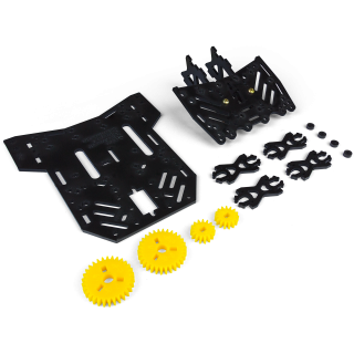
Rocket Tank - Kit de Expansão

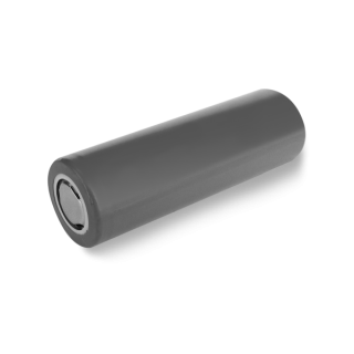
Suporte para 2 Baterias Li-Ion 18650

Porca M2.5 - 10 unidades
Note: The recommended 18650 batteries listed above are rechargeable, but must be charged using a suitable charger (such as this one, for example).
Mechanical Assembly
To assemble the Rocket Tank set with the RoboARM, first assemble the Rocket Tank following the steps in the button manual below. Remembering that the Vespa has the same drilling pattern as the Arduino UNO platform, so it can be attached to the holes indicated for the UNO on the Rocket Tank.
Rocket Tank Assembly GuideTake the opportunity then to assemble only the back of the Rocket Tank Expansion Kit, as shown on the first page of the button manual below.
Rocket Tank Expansio Kit Assembly GuideWith the Rocket Tank assembled, follow the steps in the next assembly manual to assemble the RoboARM separately.
RoboARM Assembly GuideWith both robots assembled separately, remove the base of the RoboARM to attach it to the Rocket Tank as shown in the button manual below.
RoboARM with the Rocket Tank Assembly GuideThe battery holder can be attached to the Rocket Tank's airfoil using the M2.5 x 10mm screws with the M2.5 nuts included in the tutorial's materials list, as in the complete example assembly below. Alternatively, the battery holder can be hidden between the bottom and top covers of the Rocket Tank chassis.

Electronic Assembly
With the structure of both robots mounted together, follow the electrical diagram below to make the necessary connections for robot control.

Note: the servo motors must be connected directly to the board through terminals S1 to S4. Just mind the polarity.
To fix the 18650 battery support wires, as well as those of the motors, to the Vespa, it is necessary to open and close the contacts of the removable terminal blocks on the board, as shown in the GIF below.
Coding
Now that the robot is physically assembled, we have to write the code that will be used to control it.
Libraries
The libraries used in this project are the same as those used in previous separate robot projects. Therefore, if you have already followed the steps of one of those tutorials and already installed the libraries, it is not necessary to install them again.
If you haven't followed the previous separate tutorials, you'll need to install some libraries that are used by the code so that the board performs as we want. To do so, download the necessary libraries using the button below.
Once the files are downloaded, follow the image path below in the Arduino IDE to install the libraries from the compressed file.
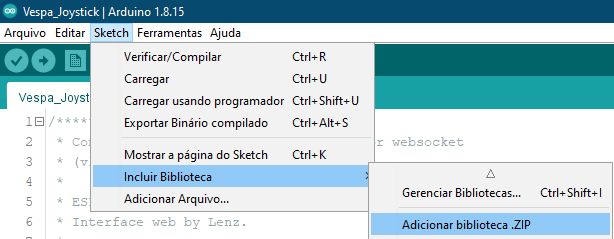
When selecting this option, a window will open with the directories of your computer. Navigate to the directory where the compressed (ZIP) files were saved and then double-click on one of the folders. This will cause the library contained in the selected file to be installed in your IDE.
As we need the three libraries available above for the code to work, it is necessary to repeat this procedure for the other two downloaded files as well.
Code
With the libraries installed, upload the following code to your Vespa. Remembering that it is necessary to follow the steps of Firts Steps with the Vespa to install all the necessary tools for its functioning, as well as to understand how to load codes in it.
Note: to record the code, keep the battery connected to the Vespa and the power switch in the "ON" position. This is necessary as servos draw a relatively high current that USB ports on computers shouldn't be able to supply, so the board may keep resetting constantly and preventing code from being written.
Understanding the Code
The code for this tutorial is basically a mash-up of the Rocket Tank and RoboARM separate control tutorials, so most of the functions are identical.
In this code, Vespa is responsible for creating its own Wi-Fi network and an asynchronous web server. With this, we can connect smartphones, tablets and even computers to the network created to access the board's server. After creating your network, the board also provides an IP address, which will be used to access the robot control web page.
The server's web page is entirely programmed in code and it is thanks to it that the control interface is presented. On the page there is mainly a joystick that gives direction to the robot. When moving the joystick, data is sent in JSON format to Vespa, which, in turn, identifies them and acts according to what was commanded by the joystick. This data is the angle at which the joystick pointer is set (referring to the angles shown in the image below) and the distance between the pointer and the center of the joystick. Then the motors are driven as expected. For example, when the pointer is up/forward, that is, at an angle between 80 and 100°, and touching the end of the joystick, the motors are driven forward at full speed using commands from the board's library.

Underneath the Rocket Tank's control joystick are the four "sliders" for controlling the RoboARM's servos. The angle at which each of the "sliders" is positioned is checked (taking the angles shown in the image below as a reference) and then the respective servos are commanded to their new positions. For example, if the first "slider" is positioned at an angle of 90°, the base servo, connected to pin S1 on the board, will be updated to the angle of 90°.

Another interesting feature of the control interface is the battery meter, which is one of the Vespa's many features. The board measures battery voltage every 5 seconds and then updates the voltage displayed on the interface. This way, you'll always know when you need to change or recharge the robot's batteries.
Most of the project's functions are monitored by the serial monitor, so you can, if you want, monitor the information on the board. To do so, just open the serial monitor on your board's serial port, with a speed of 115200 bps.
What Must Happen
After loading the code to the board, disconnect the USB cable, turn it on by the on/off switch of its circuit, and then open the list of Wi-Fi networks available on the device you will use for control (cell phone, tablet or computer ). After a few moments, a network with the name "Vespa-xx:xx" will be displayed, as in the image below, for example.

Note: Vespa Wi-Fi network suffix "xx:xx" is taken from the last characters of the board's ESP32 MAC Address to make the network unique, so don't worry if the name from the network is different from the image, as this is expected.
To establish the connection to the network, just use the password "robocore", which is the code's default password.
Remember that you can, if you want, change the name and password of the Wi-Fi network created by the board, just change these parameters in the code configuration (function void setup()).
After connecting your device to the card's network, open the browser of your choice and then access the IP address "192.168.4.1". When accessing the IP address, the project control interface page will be opened, as shown in the following image.

As soon as the Vespa is ready to be controlled, its LED L will remain lit and you will be able to move the Joystick and the "sliders" to control the movement of the robot, as in the GIF below.
Attention: the positions of the RoboARM servomotors are not limited by the program, so you must avoid forcing the movements if the parts are touching, as this could damage the servos.
Warning: Do not let batteries discharge below 6.8V. Lithium batteries must always have at least 3.4V per cell to function properly.
Conclusion
In this tutorial we continue with the robot control projects with Vespa and we saw how to control two different mechanisms simultaneously using only one Vespa.
Troubleshooting
The robot is not walking in the right direction
If the robot is not behaving as expected and as controlled by the joystick, it is likely that one of the motors has reversed polarity. Lift the robot and see which of the motors has the inverted spin when commanding the robot forward, for example. Then turn off the board, disconnect the motor terminal and invert the connection of the motor wires. This should resolve the issue.
RoboARM is hitting itself or not reaching its maximum moves
If the robot is beating itself when being controlled for some moves, or is not reaching its maximum moves, check the mechanical mounting of the servos, as it is possible that they have been mounted too close to their mechanical limits. It is also worth remembering that the "sliders" have no limitation, so follow the movement of the robot to stop it, or move it in another way, if the servos are locked, to avoid damaging them.
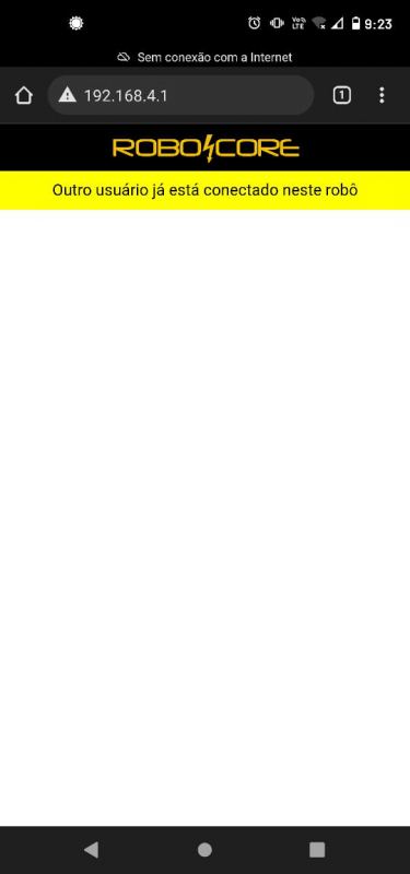
Web interface returns "Vespa ocupada"
If the web interface accessed on the Vespa shows that another user is connected to the robot, as in the image below, it is a sign that there is another cell phone connected to it, or that there was a double attempt to connect to your cell phone server. Then check that any cell phone previously used to control the robot has not automatically connected to the Vespa network and try restarting the server page.
The red LED is on
The red LED labeled R on the board is a reverse polarity indicator LED on the board, so if it is lit, it is expected that the board will not turn on as a protection. Disconnect the board power terminal and reverse the battery power supply polarity.
Unable to access IP address for controller
If the control interface is not being displayed when accessing the server's IP address, check your connection to the board's network. It is common for more modern devices to automatically disconnect from Wi-Fi networks without internet (as is the case with the network created by Vespa) to try to connect to another network. If this is happening, disable your device's automatic disconnection.