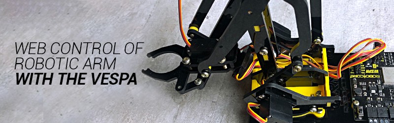
Web Control of Robotic Arm with the Vespa
Introduction
In this tutorial you will see how to control the movement of the RoboARM through your smartphone, thanks to Vespa. For this, you will assemble the RoboARM with the Vespa, assemble the electrical circuit, and then see the connection steps to access the control page.
List of Materials

Lista completa de produtos
comprar
Braço Robótico RoboARM V3

Vespa
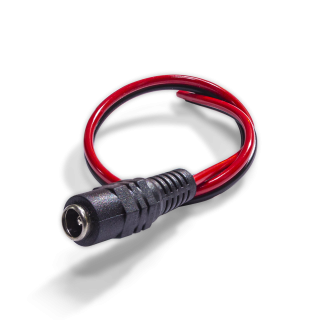
Extensor DC P4 Fêmea

Fonte Chaveada 9V 2A
Warning: before proceeding, you must follow the steps in First Steps with the Vespa, as they teach you how to install the essential tools for using the board.
Mechanical Assembly
The first step to develop the project for this tutorial is to mechanically assemble the RoboARM and fix the Vespa on its base. To do so, follow the RoboARM assembly guide using the button below.
RoboARM Assembly GuideVespa has the same fixing hole pattern as the Arduino UNO platform boards, so take advantage of this platform's hole available at the base of the structure to fix it.
Electronic Assembly
With the mechanical part ready, assemble the circuit in the image below with your Vespa.

Note: the servo motors can be connected directly to the board through terminals S1 to S4. Just mind the polarity.
To fix the jumpers between the P4 adapter and the Vespa, it is necessary to open and close the contacts of the removable terminal blocks on the board and the adapter terminal, as shown in the GIF below.
Coding
Now that the robot is physically assembled, we have to write the code that will be used to control it.
Libraries
Before uploading the example code to the board, we have to install some libraries that are used by the code so that the board executes what we want. To do so, download the necessary libraries using the button below.
Once the files are downloaded, follow the image path below in the Arduino IDE to install the libraries from the compressed file.
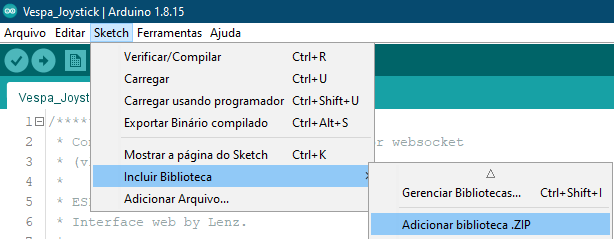
When selecting this option, a window will open with the directories of your computer. Navigate to the directory where the compressed (ZIP) files were saved and then double-click on one of the folders. This will cause the library contained in the selected file to be installed in your IDE.
As we need the three libraries available above for the code to work, it is necessary to repeat this procedure for the other two downloaded files as well.
Code
With the libraries installed, upload the following code to your Vespa. Remembering that it is necessary to follow the steps of initial settings of the board to install all the necessary tools for its functioning, as well as to understand how to load codes in it.
Understanding the Code
In this code, Vespa is responsible for creating its own Wi-Fi network and an asynchronous web server. With this, we can connect smartphones, tablets and even computers to the network created to access the board's server. After creating your network, the board also provides an IP address, which will be used to access the robot control web page.
The server's web page is entirely programmed in code, and it is thanks to it that the control interface is presented. On the page, four "sliders" are displayed, where each one is responsible for controlling the position of one of the RoboARM's servomotors. When moving one of the "sliders", the page forwards data in JSON format to the Vespa, which in turn interprets them and then controls the respective servo to the updated position.
Another interesting feature of the control interface is the board's input voltage meter, which is one of the Vespa's many features. The board measures its input voltage every 5 seconds and then updates the voltage displayed on the interface. Perhaps this is not very important for using power supplies, as the voltage will always be constant, but it can be very useful if you want to use the RoboARM with batteries, as you will always know when it is necessary to change or recharge the robot's batteries.
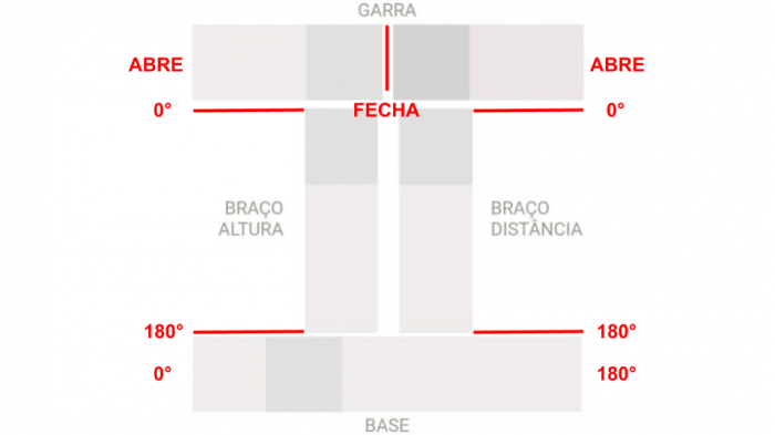
The main function of this code is in controlling the servomotors, since it is responsible for moving the RoboARM. In it, the angle at which each of the "sliders" is positioned is checked (taking the angles shown in the image below as a reference) and then the respective servos are commanded to their new positions. For example, if the first "slider" is positioned at an angle of 90°, the base servo, connected to pin S1 on the board, will be updated to the angle of 90°.
Most of the project's functions are monitored by the serial monitor, so you can, if you want, monitor the information on the board. To do so, just open the serial monitor on your board's serial port, with a speed of 115200 bps.
What Must Happen
After loading the code to the board, disconnect the USB cable, turn it on by the on/off switch of its circuit, and then open the list of Wi-Fi networks available on the device you will use for control (smartphone, tablet or computer ). After a few moments, a network with the name "Vespa-xx:xx" will be displayed, as in the image below, for example.

Note: Vespa Wi-Fi network suffix "xx:xx" is taken from the last characters of the board's ESP32 MAC Address to make the network unique, so don't worry if the name from the network is different from the image, as this is expected.
To establish the connection to the network, just use the password "rc-vespa", which is the code's default password.
Remember that you can, if you want, change the name and password of the Wi-Fi network created by the board, just change these parameters in the code configuration (function void setup()).
After connecting your device to the board's network, open the browser of your choice and then access the IP address "192.168.4.1". When accessing the IP address, the project control interface page will be opened, as shown in the following image.

Once the Vespa is ready to be controlled, its LED L will remain turned on and you will be able to move the "sliders" to control the movement of the robot, as in the GIF below.
Attention: the positions of the motors are not limited by the program, so you must avoid forcing the movements if the parts are touching, as this could damage the servos.
Conclusion
In this tutorial we saw how to take advantage of Vespa's functionalities to make a remote control of robotic arms and now you can enjoy the project created for fun!
Going Beyond
In addition to the remote control of the RoboARM, it is also possible to use the same concepts to control robots with wheels, as shown in Rocket Tank remote control tutorial.
Troubleshooting
The Robot is Hitting itself or not Reaching its Maximum Movements
If the robot is beating itself when being controlled for some moves, or is not reaching its maximum moves, check the mechanical mounting of the servos, as it is possible that they have been mounted too close to their mechanical limits. It is also worth remembering that the "sliders" have no limitation, so follow the movement of the robot to stop it, or move it in another way, if the servos are locked, to avoid damaging them.
The Red LED is On
The red LED labeled R on the board is a reverse polarity indicator LED on the board, so if it is lit, it is expected that the board will not turn on as a protection. Disconnect the board power terminal and reverse the battery power supply polarity.
Unable to access IP address for control
If the control interface is not being displayed when accessing the server's IP address, check your connection to the board's network. It is common for more modern devices to automatically disconnect from Wi-Fi networks without internet (as is the case with the network created by Vespa) to try to connect to another network. If this is happening, disable your device's automatic disconnection.