Beginner Robotics Kit - 8. Line Follower Robot

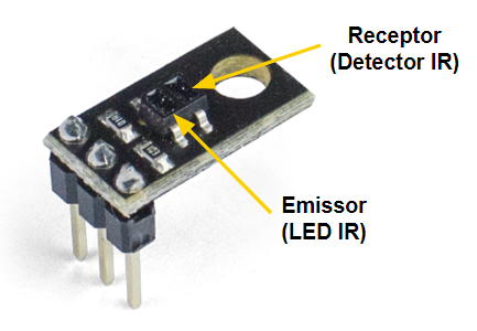
The Starter Kit for Robotics comes with a pair of Analog QRE Reflectance Sensors for line detection. These sensors work by emitting a beam of infrared (IR) light towards the surface below the robot and measuring how much light is reflected. On the sensor, you will notice that there are two small rectangles. One is the IR emitter and the other is the detector.
Line sensors work best when they are close to the surface below the robot. The sensor must be about 3mm above the ground. This is a great distance for the IR emitter to illuminate the surface and read the reflected light. But rest assured, if you followed the assembly step-by-step correctly, the sensors will be well positioned.
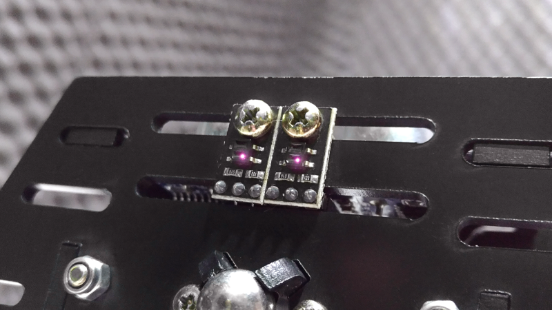
Note: Human eyes are not sensitive to infrared light, so unless you are a superhero, you will not be able to see the light emitted by the sensors. But if you use a CCD camera, like the one on your smartphone, you will be able to see small points of light coming out of your sensors.
In this example, we will simply read and print the values of our Line Sensors. It is interesting that you test the sensors in different scenarios so that you can understand their behavior.
Load this sample code into the Julieta board. To do this, go to: File-> Examples-> RoboCore Falcon Robot Library-> Exp4_1_LineFollowing or copy and paste the sample code below.
After loading the code for your robot, open the Serial Monitor to view the reading of your sensors. You should see a window like this:
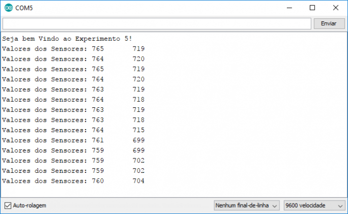
If you made the correct connections, in the first column you will have the values read by the left sensor and in the second column the values read by the right sensor.
With the robot connected to your computer, perform the following tests:
To set up a connection between the robot and your computer, it is necessary to use the Serial Object in Arduino. In setup() , the Serial.begin(9600); command initializes the Arduino Serial and determines the speed at which data is transmitted and received between the robot and the computer. The value of 9600 defines the baud rate, that is, the number of bits per second. This is a good speed for most applications, but other speeds are supported by the Arduino, such as: 300, 1200, 2400, 4800, 9600, 14400, 19200, 28800, 38400, 57600, and 115200.
To send data from the robot to your computer, you can basically use two commands: Serial.print(""); and Serial.println(""); . The first command, Serial.print(""); simply prints the text in quotes ("") or some data (in the form of a number or variable) to the Serial bus - this is shown in the Monitor Serial. The second command, Serial.println(""); is the same, but adds a carriage return and newline character, moving the cursor to the beginning of the next line.
The FalconRobotLineSensor class has several methods, but for this specific project the main one is xxxx.read(); . This method returns a value between 0 and 1023 based on the input voltage of the sensor. Remember that xxxx represents the name of the object (in this case, lineSensor1 or lineSensor2).
Now that you understand how infrared reflectance sensors work, it's time to learn how to make your robot follow the line!
A curiosity: did you know that there are several competitions for line-following robots in all parts of the world, including world robotics championship that RoboCore organizes every year? That's right, the basic concepts that you will learn here can be used for those who know how to build a competition robot!
The algorithm for keeping the robot on track is quite simple. Note that the main objective is to always keep the two sensors on the line, as this way the robot will be centered on the path it must take. Therefore, the basic logic that must be implemented is:
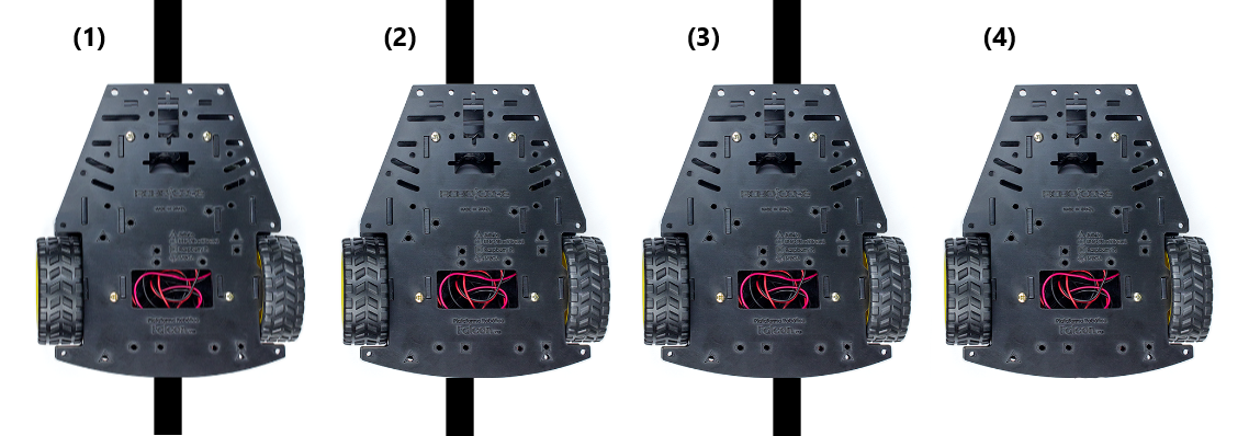
Note that there is also a fourth hypothesis where the two sensors are out of line (4), but in this tutorial only the first three situations will be considered, leaving it up to you to choose what to do when the latter occurs.
Upload this sample code to your Falcon Platform. To do this, go to: File-> Examples-> RoboCore Falcon Robot Library-> Exp4_2_LineFollowing or copy and paste the sample code below.
After uploading the code to your robot, place it on the white sheet with tape you made in the last chapter. Try to replicate the hypotheses mentioned above and check if the robot responds according to the logic necessary to follow the line. That is, place the robot with the two sensors on top of the line and see if the two motors rotate in the same direction, making the robot go forward. Do the same for cases where only one sensor is on the line and see if the robot turns in the right direction.
The coolest part about building a robot that follows the line is to observe it by taking a route alone. So let's build a small circuit for your robot.

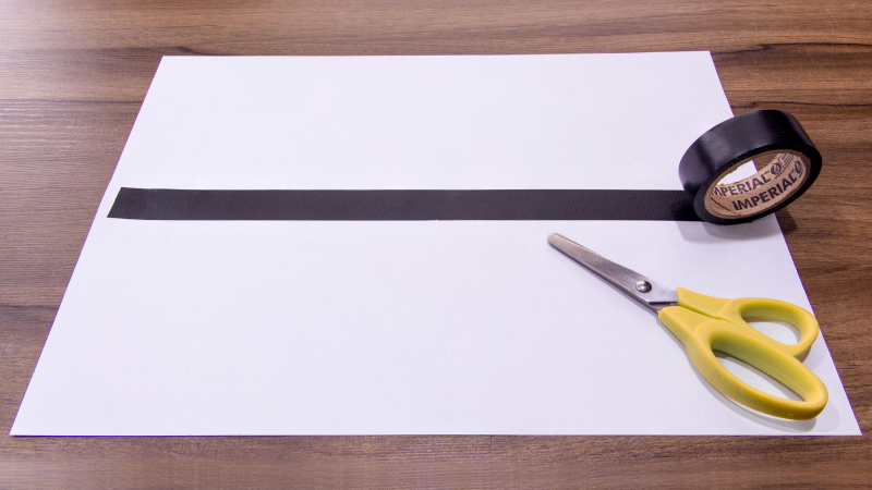
To do this, simply apply the black tape you received with the Kit on a clear surface large enough for your circuit. Remember that it is important that there is a good difference in reflectance between the black tape and the surface where the track is built so that the robot can identify the line.
It is important that the surface is clear, flat and without large undulations or gaps. You can build on a table, on cardboards or even on a floor that does not have major depressions. Also pay attention to the spacing between the lines, because if the lines of the track are too close, the chances of the robot getting lost increase considerably.
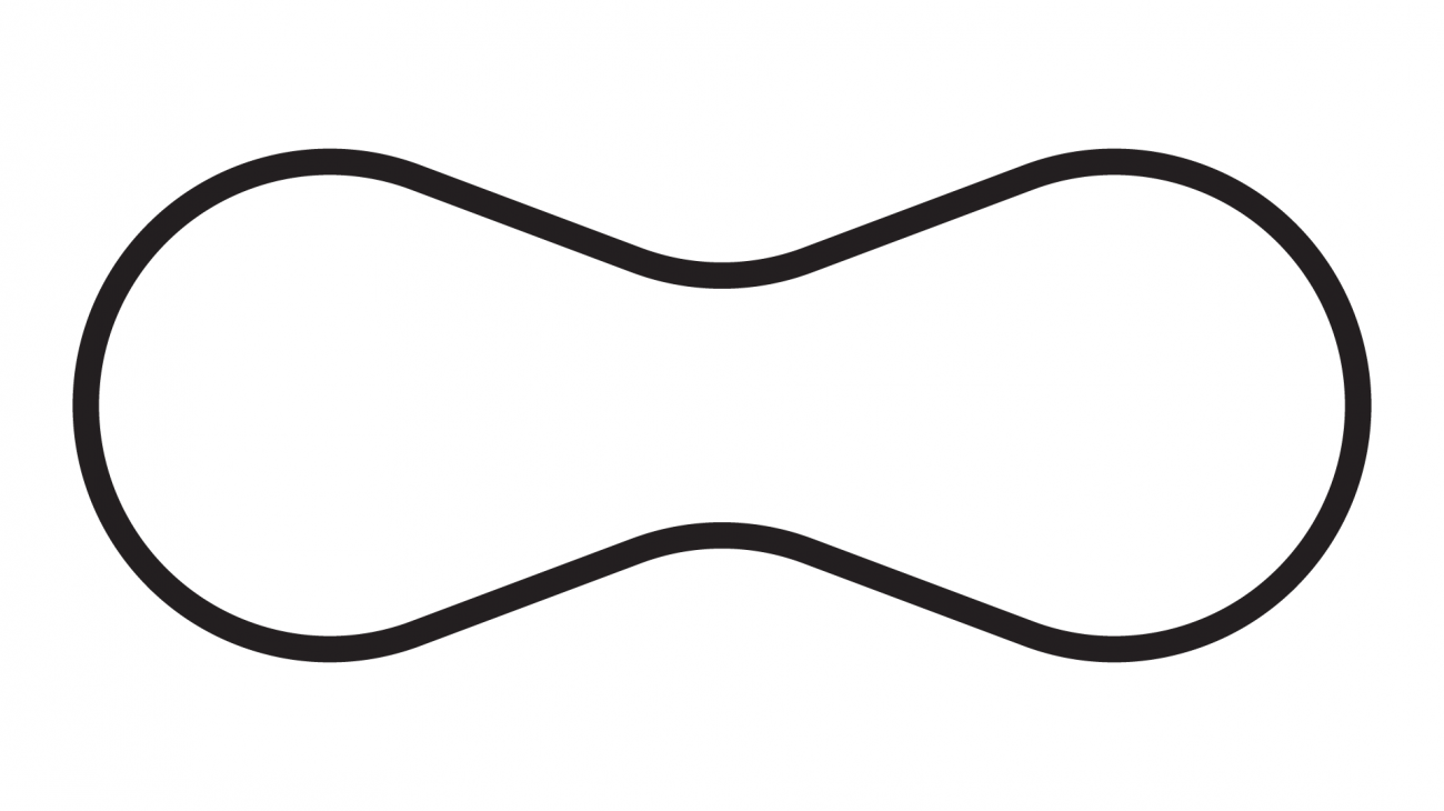
The image above shows a good example of a track to build. It is a simple model and your robot will probably have no problems following the route.
In this example, two constants were used. The LINETHRESHOLD constant and the SPEED constant. The first, LINETHRESHOLD , defines the boundary between the dark line and the track surface. That is, if the sensor value is below the limit, then the sensor is on the white surface, if it is above the limit, then the sensor is on the line. The second, SPEED , defines the nominal speed of the engines when it must move forward.
Note that in this code the expression #define was used. This word allows the creation of constants without taking up the memory of your Arduino's variables.
The part of the code where the logic itself is implemented is in the lines below. You can observe 3 conditionals. Each of them deals with the cases mentioned at the beginning of this chapter. The first if takes care of the occasion where the two sensors are on the line, setting the motor speeds to the rated speed, making the robot go in a straight line.
The second conditional, else if takes care of the case where only the right sensor is on the line and the robot must turn to the right. In that case, the speed of the motor on the right is reduced and the speed of the motor on the left is increased. In the last if of the program, it takes care of the last case, where the robot must turn to the left.
Here is an explanation of the if and else if routine, both used in the code. We use the routines to express what we want to be done if a condition is met, and what we want to happen if that same condition is not met. This is easier to understand if we put it the way we think. Let's see:
Note that the && symbol means that both conditionals have to be met for an action to be performed.
Tip: there is a very popular control technique called PID that is widely used for the most diverse applications where it is necessary to stabilize a system with inputs and outputs, such as a robot following line, for example. To learn more, click here . < br>
Line sensors work best when they are close to the surface below the robot. The sensor must be about 3mm above the ground. This is a great distance for the IR emitter to illuminate the surface and read the reflected light. But rest assured, if you followed the assembly step-by-step correctly, the sensors will be well positioned.
Note: Human eyes are not sensitive to infrared light, so unless you are a superhero, you will not be able to see the light emitted by the sensors. But if you use a CCD camera, like the one on your smartphone, you will be able to see small points of light coming out of your sensors.
Seeing the Line
In this example, we will simply read and print the values of our Line Sensors. It is interesting that you test the sensors in different scenarios so that you can understand their behavior.
Load this sample code into the Julieta board. To do this, go to: File-> Examples-> RoboCore Falcon Robot Library-> Exp4_1_LineFollowing or copy and paste the sample code below.
After loading the code for your robot, open the Serial Monitor to view the reading of your sensors. You should see a window like this:
If you made the correct connections, in the first column you will have the values read by the left sensor and in the second column the values read by the right sensor.
With the robot connected to your computer, perform the following tests:
- Place your robot on your table. What are the values read by the two sensors?
- Place it on the sheet with tape. What are the values read on the tape? What about the white surface?
- With the robot still on the table, turn off the ambient lights or cover it with a blanket or something. What happens to the values read? What do you think is causing this?
- Move the robot slowly to the edge of the table. Observe the readings as the sensors approach the edge of the table. What are the values of the sensors when they are off the table?
Understanding the code
To set up a connection between the robot and your computer, it is necessary to use the Serial Object in Arduino. In setup() , the Serial.begin(9600); command initializes the Arduino Serial and determines the speed at which data is transmitted and received between the robot and the computer. The value of 9600 defines the baud rate, that is, the number of bits per second. This is a good speed for most applications, but other speeds are supported by the Arduino, such as: 300, 1200, 2400, 4800, 9600, 14400, 19200, 28800, 38400, 57600, and 115200.
To send data from the robot to your computer, you can basically use two commands: Serial.print(""); and Serial.println(""); . The first command, Serial.print(""); simply prints the text in quotes ("") or some data (in the form of a number or variable) to the Serial bus - this is shown in the Monitor Serial. The second command, Serial.println(""); is the same, but adds a carriage return and newline character, moving the cursor to the beginning of the next line.
Printing Special Characters
There are some special characters that you can print. Below you can see some that are used in C and C ++:| Code | Description |
| \t | TAB character |
| \" | Double quotes |
| \' | Single quotes |
| \n | CRLF - new line |
FalconRobot Library
The FalconRobotLineSensor is an object created to facilitate interaction with the line sensors that come with the Kit. In the robot, the line sensors were connected to Julieta's A2 and A3 pins. For this reason, in the lines below, an object was created to take care of the reading of each sensor.The FalconRobotLineSensor class has several methods, but for this specific project the main one is xxxx.read(); . This method returns a value between 0 and 1023 based on the input voltage of the sensor. Remember that xxxx represents the name of the object (in this case, lineSensor1 or lineSensor2).
Troubleshooting
Nothing is being printed on the Serial Monitor!
- Check that the baud rate has been set up correctly on your serial monitor. There is a menu in the lower right corner, it must be configured for the 9600 baud rate.
The value of my sensor does not change!
- Check that the sensors have been correctly connected to your Juliet board.
- Try to exchange one sensor with another.
Now that you understand how infrared reflectance sensors work, it's time to learn how to make your robot follow the line!
A curiosity: did you know that there are several competitions for line-following robots in all parts of the world, including world robotics championship that RoboCore organizes every year? That's right, the basic concepts that you will learn here can be used for those who know how to build a competition robot!
Following the Line
The algorithm for keeping the robot on track is quite simple. Note that the main objective is to always keep the two sensors on the line, as this way the robot will be centered on the path it must take. Therefore, the basic logic that must be implemented is:
- If the two sensors are on the line, move forward (left and right engine at the same speed).
- If the left sensor is on the line and the right sensor is off the line, turn to the left (left engine a little slower and the right engine a little faster).
- If the right sensor is on the line and the left sensor is off the line, turn to the right (right engine a little slower and the left engine a little faster).
Note that there is also a fourth hypothesis where the two sensors are out of line (4), but in this tutorial only the first three situations will be considered, leaving it up to you to choose what to do when the latter occurs.
Upload this sample code to your Falcon Platform. To do this, go to: File-> Examples-> RoboCore Falcon Robot Library-> Exp4_2_LineFollowing or copy and paste the sample code below.
After uploading the code to your robot, place it on the white sheet with tape you made in the last chapter. Try to replicate the hypotheses mentioned above and check if the robot responds according to the logic necessary to follow the line. That is, place the robot with the two sensors on top of the line and see if the two motors rotate in the same direction, making the robot go forward. Do the same for cases where only one sensor is on the line and see if the robot turns in the right direction.
Exercise: Building a runway
The coolest part about building a robot that follows the line is to observe it by taking a route alone. So let's build a small circuit for your robot.
To do this, simply apply the black tape you received with the Kit on a clear surface large enough for your circuit. Remember that it is important that there is a good difference in reflectance between the black tape and the surface where the track is built so that the robot can identify the line.
It is important that the surface is clear, flat and without large undulations or gaps. You can build on a table, on cardboards or even on a floor that does not have major depressions. Also pay attention to the spacing between the lines, because if the lines of the track are too close, the chances of the robot getting lost increase considerably.
Attention: if you build your track on an elevated surface, such as a table, be very attentive whenever you place the robot to follow, as eventually it may leave route and even fall off the table.
The image above shows a good example of a track to build. It is a simple model and your robot will probably have no problems following the route.
Understanding the code
In this example, two constants were used. The LINETHRESHOLD constant and the SPEED constant. The first, LINETHRESHOLD , defines the boundary between the dark line and the track surface. That is, if the sensor value is below the limit, then the sensor is on the white surface, if it is above the limit, then the sensor is on the line. The second, SPEED , defines the nominal speed of the engines when it must move forward.
Note that in this code the expression #define was used. This word allows the creation of constants without taking up the memory of your Arduino's variables.
The part of the code where the logic itself is implemented is in the lines below. You can observe 3 conditionals. Each of them deals with the cases mentioned at the beginning of this chapter. The first if takes care of the occasion where the two sensors are on the line, setting the motor speeds to the rated speed, making the robot go in a straight line.
The second conditional, else if takes care of the case where only the right sensor is on the line and the robot must turn to the right. In that case, the speed of the motor on the right is reduced and the speed of the motor on the left is increased. In the last if of the program, it takes care of the last case, where the robot must turn to the left.
Here is an explanation of the if and else if routine, both used in the code. We use the routines to express what we want to be done if a condition is met, and what we want to happen if that same condition is not met. This is easier to understand if we put it the way we think. Let's see:
Note that the && symbol means that both conditionals have to be met for an action to be performed.
Going Beyond
Going faster
This code really only works when the robot is moving slowly and sometimes it will go off the line in sharp curves. What can you do to make it work better?Tip: there is a very popular control technique called PID that is widely used for the most diverse applications where it is necessary to stabilize a system with inputs and outputs, such as a robot following line, for example. To learn more, click here . < br>
Other related experiments
With the concepts learned in this chapter you can develop other cool experiments. For example, would you be able to modify the code in such a way that, when placing the robot inside a square, circle or any other closed geometric shape, it remains within the enclosed space?Troubleshooting
The robot vibrates a lot when it comes to moving!
- By adjusting the nominal speed values, the line limit value and the values that are incremented and decremented when turning, you will be able to make the robot follow the course more smoothly.
The robot does not follow the line
- Check the connections of the sensors and motors, as it is possible that some connection is inverted and the circuit does not correspond with the logic implemented in the code.